Lab 3 Report
Introduction
In this lab, a design was implemented to program the MCU to configure two timers, one used to control frequency and one used to control delay of a note. The timers were then used to play a song with accurate notes and timing.
Design and Testing Methodology
Design Overview
The first step in the design was to develop the struct for the TIM using timers 15 and 16. This was done in the header file. The next step was to determine what registers needed to be written to and in what order for timers 15 and 16 to be configured correctly. One was configured to run a delay_millis() function and another for pwm_update() which controlled the frequency changes of the notes. Lastly, in the main.c file configuration steps were taken for GPIO pin setup and PLL clock setup. Then a loop was used to play each note in the song array.
Testing Procedure
The design was tested by using the segger step through function to make sure the registers were changing as expected. Then the MCU output was measured with an oscilliscope to ensure the correct ssqaure wave behavior with correct frequency was outputed. Lastly, plug it into the speaker and listen to the fruits of my labor.
Technical Documentation
Source Code
Calculations
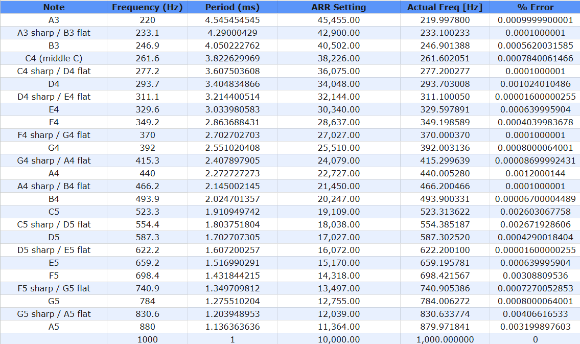
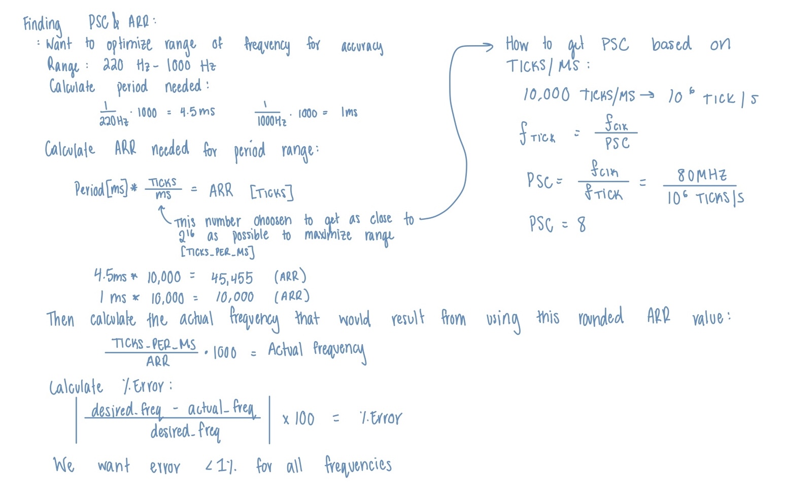
The table above shows the calculations for the ARR values and actual frequencies to then calculate the error. Below is a general walk through of the equations/steps used.
Below are the minimum and maximum calculations for the frequency and durations. 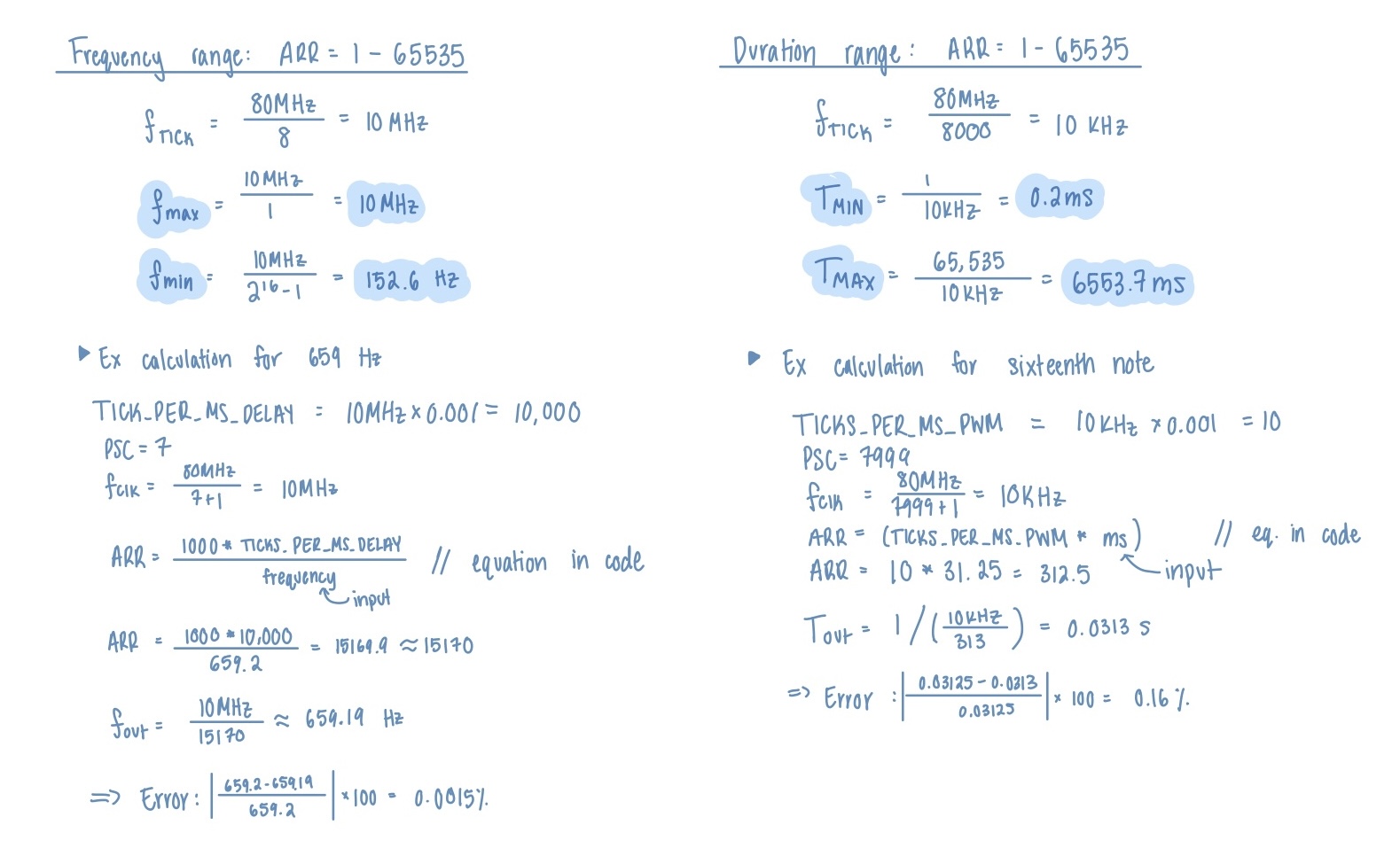
Schematics
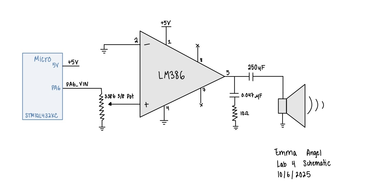
The example schematic Figure 9-1 in the LM368 datasheet was built using the default gain of 20. A potienometer was used for volume control at the input of the op amp.
Results and Discussion
Conclusion
The design was successful with fur elise playing at the right pitch and tempo. Then a custom song was also played. I spent 25 hours on this lab.
AI Prototype Summary
The AI suggested that I used TIM2 which is not what I used. I used 15 and 16 because I needed two timers that were similar and could use the same struct. She calculated the PSC of 79 which is sort of in the middle of the PSCs I calculated. I used two different prescalers to match the needs of the range for each individual purpose. When it came to relevant registers I think she got the all. Maybe not all the specfic bits I had to write to but defintely got all the registers right. I didn’t even both giving the reference manual because of this. The example code is very similar to what I used except I had specific functions to update the code. She also got the part where you configure the GPIO as an alt function.