Lab 5 Report
Introduction
In this lab, a design was implemented to program the MCU to read from a quadrature encoder using interrupts to measure the velocity of the motor and display the readings.
Design and Testing Methodology
Design Overview
The first step in the design was to enable global interrupts and set up two external interrupts one for each encoder input. The interrupts were triggered on both the rising and falling edge of the input. Each time an interrupt was triggered the encoder count was updated based on whether it was positive or negative direction of the motor. The velocity was calculated and printed once a second.
Testing Procedure
The design was tested by using the segger step through function to make sure the registers were changing as expected. Then the motor was connected to be able to read the output being printed and debugging could be done that way.
Technical Documentation
Source Code
Calculations
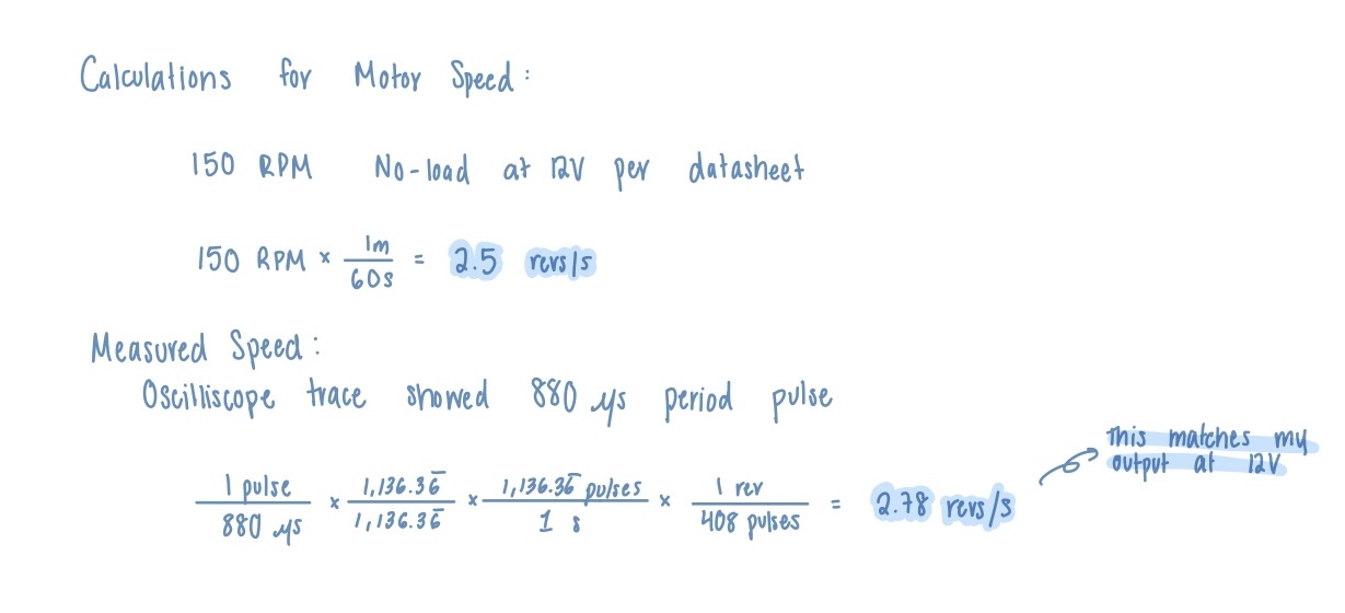
This shows calculations for the theoretical motor speed and then the motor speed calculated using an actual period measurement of the motor 12V.
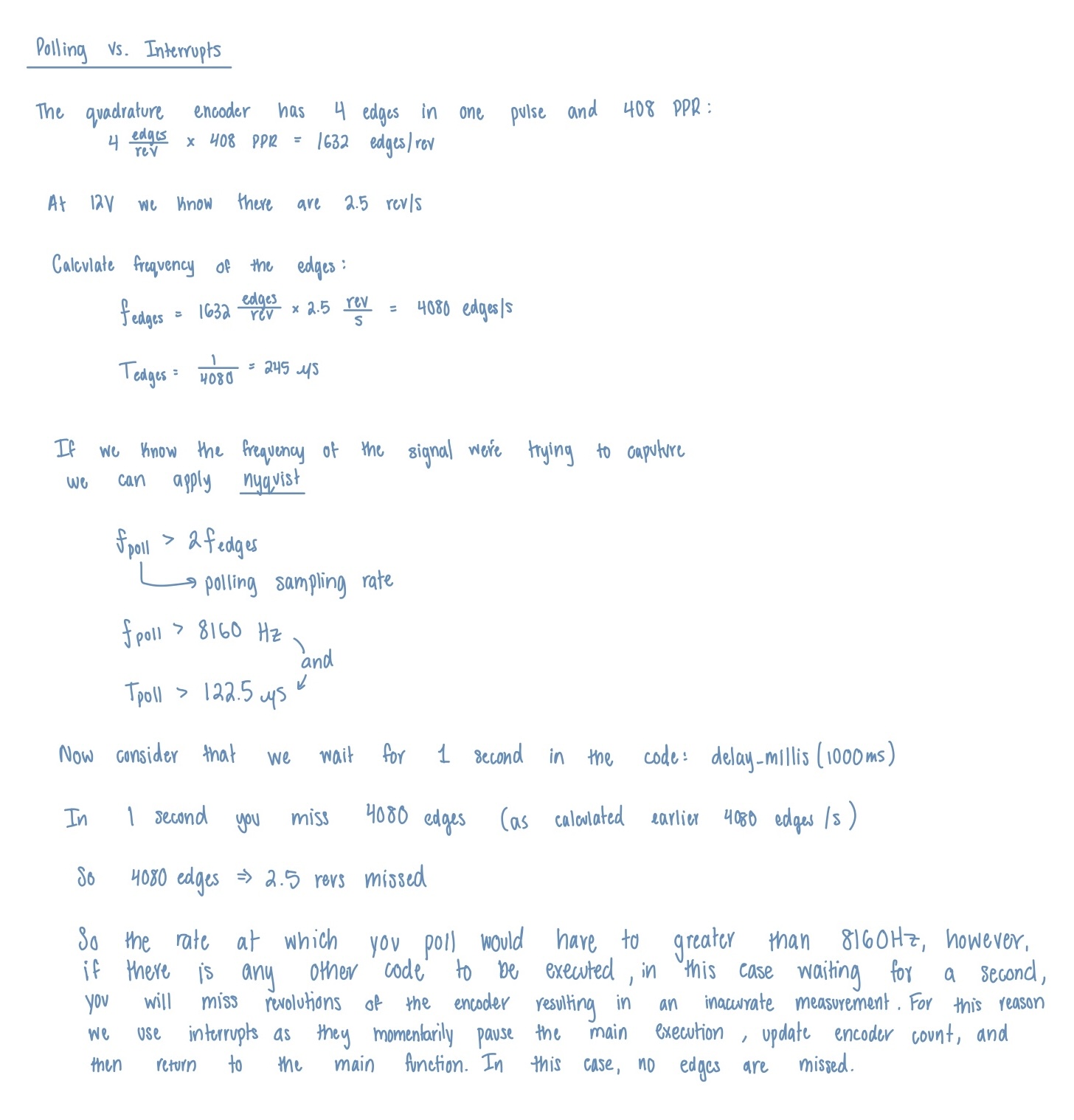
The above explains the differences between polling and interrupts and shows the error in the velocity measurement when using polling compared to interrupts.
Flowchart
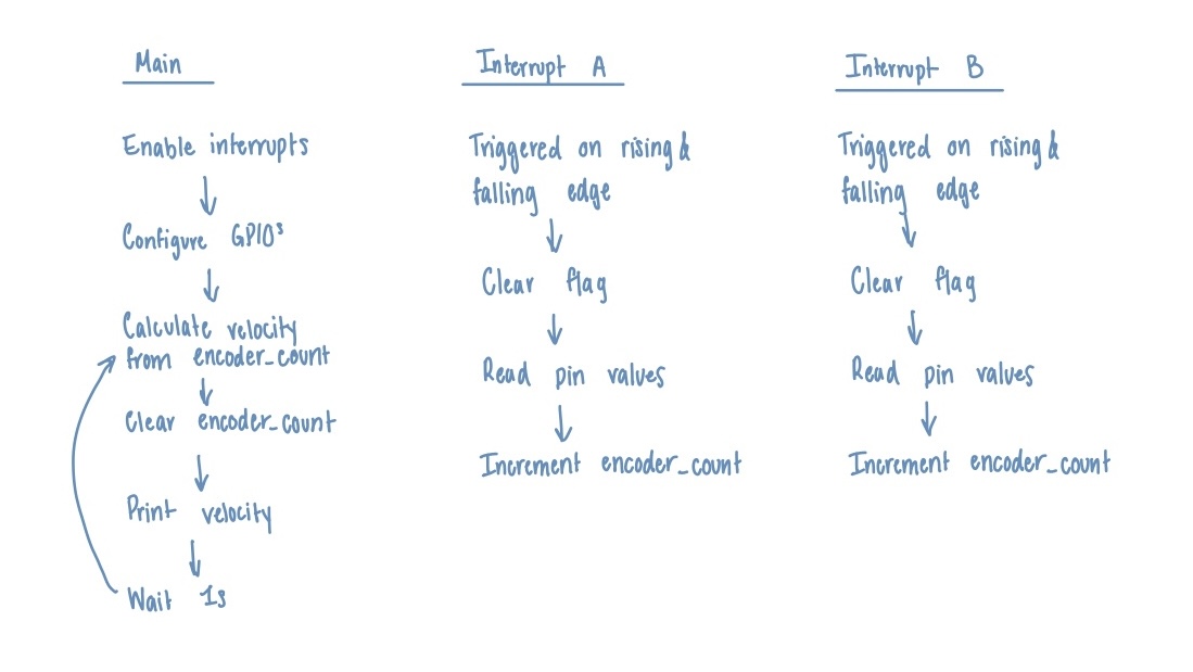
The flowchart shows the general code executed by the main function adn then the code executed in the interrupts. The interrupts update the encoder_count and the main function uses that to compute the velocity once a second.
Schematics
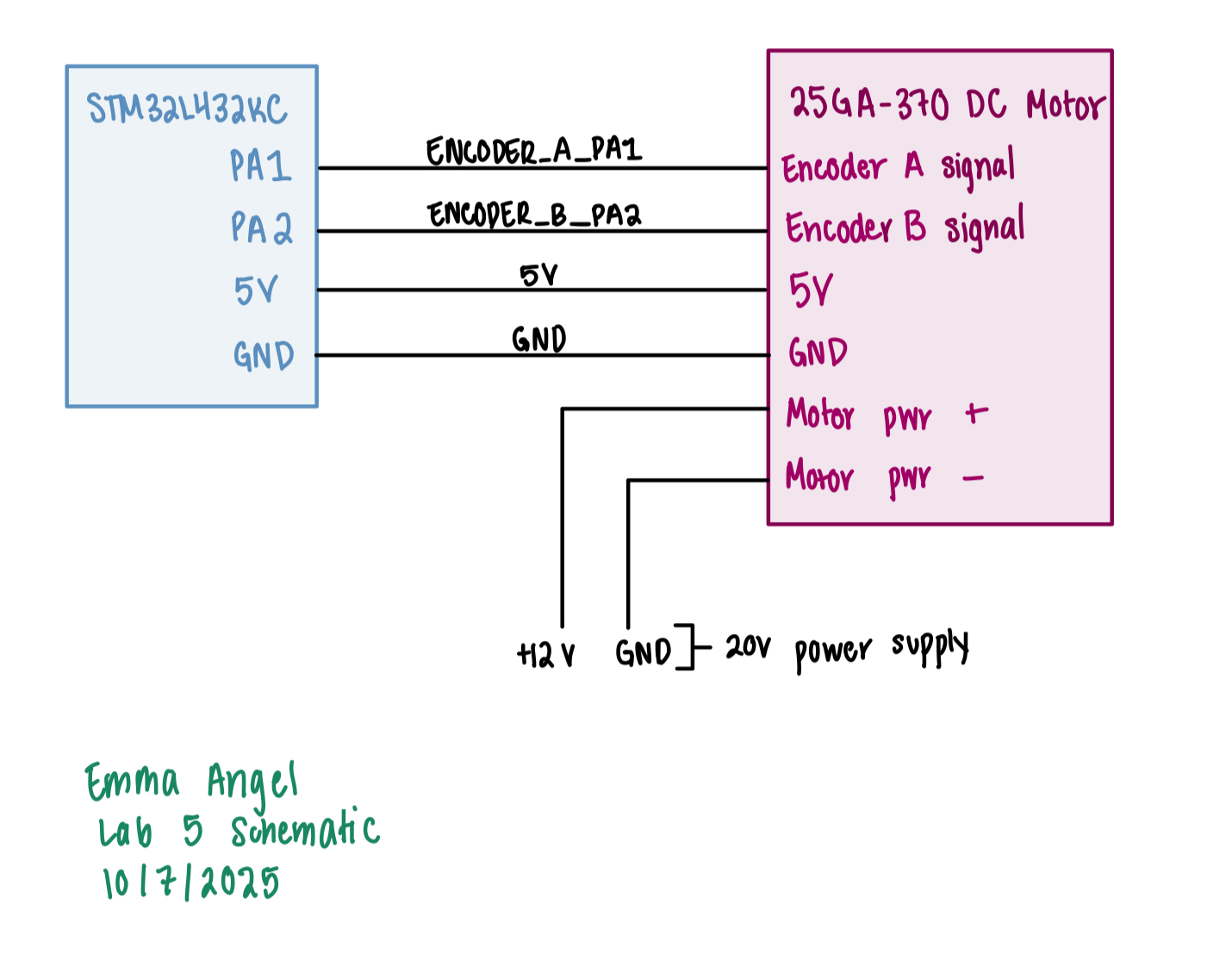
Pinout for the motor was taken from the datasheet on the website. Connecte to the MCU and then powered the motor using an external power supply.
Results and Discussion
Conclusion
The design was successful with the correct speed of the motor being printed at one a second with the correct direction I spent 15 hours on this lab.
AI Prototype Summary
I had to give AI prototype some of my code for it see how to write the registers so that I can use it with the same libraries to run. I ran the AI code with the motor and it produced -0.3 revs/s at 10V which is not anywhere close to the true value of around 2.5 rev/s that it should be reading. The AI code is shown below. I ended up giving it some of my code so it ended up structuring its own code similar to mine.